ROBOVAC
Industrial size Autonomous Vacuum Cleaner
iRobot’s Roomba, Eufy RoboVac – and more. These devices zip and zoom around homes to autonomously clean floors, providing an effortless, quiet, and continuously-running solution to dirty floors. They also serve as connections between advances in robotics and users at home.
We’ve seen autonomous vacuum cleaners in living rooms around the world for years, but we have yet to see them adapted for the shop. Our team noticed the challenges faced by shop-owners who want wood shop floors clear of saw dust, chefs who want floors food-free, and other hands-on professionals who want to maximize both productivity and cleanliness.
We sought to solve this problem to improve the lives of our users, and to tackle some technical challenges yet unsolved. Further constraints were a $500 budget, and 3 months from
conception to execution.
To solve this problem we used the following software and hardware:
Arduino Mega
Ultrasonic distance sensor
Windshield wiper motors
Motor controller
Voltage regulator
LCD display
Laser Cut
Prusa 3D Printer
Lathe
Hand Tools
Our solution includes 3 main parts:
Mechanical,
Electrical and
Software
Mechanical
The main goals of the hardware were to facilitate the safe movement of the roomba through a room, while being able to clean up the floor in a time and energy efficient manner. Challenges we faced throughout were optimizing suction and air flow and minimizing sound. We also were limited by manufacturing methods available to us – such as laser cutting and 3D printing.
The most challenging parts include:
Vacuum (Impeller)
Nozzle connection
Here you can see the necessary pictures for them:
Vacuum ( Impeller )


Electrical
One of the main parts of this project was having the proper electrical connections
between the software and the hardware. The electrical aspects include the sensors, batteries, and more to provide power to every electrical part.
To avoid any collision, ultrasonic distance sensors are used.
To be able to more robust and adaptable to most shops, drill batteries are used to power the vehicle.
The picture below features the battery holders on the left, the screen we used in the middle and the necessary wiring for the sensors on the right.

Software
Algorithm
The motion algorithm for our robot is quite simple – it drives forward, and when it senses an obstacle, it makes a U-turn until the floor is cleaned. It senses an obstacle and initiates a turn when one sensor reads an average of five readings below a particular threshold. The robot
decides which way to turn initially based on if it detects obstacles on one side, then turns the opposite way.
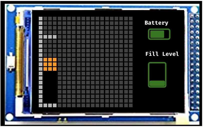
The Screen
As the robot moves, it updates its place in space by changing the location of zeroes on the matrix to reflect its current location. The code for this is as follows: The interrupt pin reads a change from the encoder. The number of changes is converted to how much the encoder has rotated. This number is tallied up, and is converted to a distance using the circumference equation, and the radius of small wheels attached to the encoders. We calculated this for two
encoders to also calculate rotation. The difference between this distance and the previous distance is calculated, which allows the matrix to be updated and for location to be tracked with
accuracy equivalent to the distance between the encoder slots. We learned about interrupts, and how useful they are to track position even while the rest of the algorithm is being executed.
The algorithm looks like this:

The screen looks like this: